-
Dreambox 500 Devre şeması
-
http://www.uydudoktoru.com/dosyalar/...ydudoktoru.zip
Dreambox 500 Devre şemasını yukardaki linkte bulabilirsiniz..(Schematic diagram DM500)
-
30 Nisan 2012 Pazartesi
Dreambox 500 Devre şeması

24 Nisan 2012 Salı
FM Verici devreleri pdf dergileri
-
FM Verici devreleri pdf dergileri
- fmvericidevreleripdfdergiler_uydudoktoru.com.rar
Yukardaki linkten FM Verici devreleri pdf dergilerini indirebilirsiniz..
-
17 Nisan 2012 Salı
Kamuoyuna duyurulur
-
- Gıda Tarım ve Hayvancılık Bakanlığının yaptığı kontroller sonucunda sahip olduğu bilgileri, 5996 Sayılı Veteriner Hizmetleri, Bitki Sağlığı, Gıda ve Yem Kanun’unun 31 inci maddesinin 6 ncı fıkrası uyarınca kamuoyunun bilgisine sunabileceği hükme bağlanmıştır. Ayrıca, 17 Aralık 2011 tarihli Gıda ve Yemin Resmi Kontrolüne Dair Yönetmeliğin 8 inci maddesi gereğince laboratuvar sonucu ile taklit ve tağşiş yapıldığı kesinleşen gıda ve yemi üreten/ithal eden firmanın adı, ürün adı, markası, parti ve/veya seri numarasının Bakanlık resmi internet sitesinde Bakanlıkça kamuoyunun bilgisine sunabileceği hükmü çerçevesinde, laboratuvar sonuçları olumsuz bulunan ürün/firma bilgileri aşağıda yer almaktadır. Kamuoyunun bilgisine sunulur.
ALıntı linki için tıklayınız
-

15 Nisan 2012 Pazar
Kısa mesafe için 3V FM Transmitter - 88MHz , 108MHz
-
Kısa mesafe için 3V FM Transmitter - 88MHz , 108MHz
-
- Bobin 1: Sargı tel 1 mm kalınlığında ve izole edilmelidir. turnike sayısı:. 3.5 5mm çekirdek ve kullanılması gereken her turda arasındaki mesafe 1 mm olmalıdır.
- Kullanabileceğiniz BF199 yerine BFR90.
- diyot Eğer varicap bulmak yapabilirsiniz değil, iki kullanabilirsiniz BB405 yerine.
Açıklama
Verici Özellikleri:
Besleme Gerilimi:3 V DC
Akımı: 21mA
Çıkış Frekans: 88MHz - 108MHz
Modülasyon: FM
Frekans Shift: ± 30KHz
Giriş: Elektret mikrofon veya başka bir giriş ses kaynağı
bir devre parçası önemli oluşmaktadır Colpitts tip osilatör. C3, C4, C5, C6, CD1-CD2 ve L1 frekansını belirler. BF982 ve çift kapı MOSFET osilatör parçaları aktif. yüksek MOSFET kapısının ne zaman giriş empedansı olan girişler, LC tank etkilenmez. Ancak transistörler vardiya kuvvet LC tank ve neden faz.
İki sürücü aşamalarda osilatör gelen anten ayırmak eklenir. İlk aşamada (BF199) osilatör sinyal düşük güçlendirir ve yük sabit eser olarak. İkinci aşamada (BFR90) daha fazla anten bazı aracılığıyla sinyal gidiyor güçlendirir. Kısa bir bakır tel burada anteni olarak kullanılabilir olabilir. büyük takma bir anten güç çıkışı düşük olduğu için bu devre gereksizdir.
Notlar
-

14 Nisan 2012 Cumartesi
10 MHZ 4 Watt AM Radyo Verici Devresi
-
10 MHZ 4 Watt AM Radyo Verici Devresi
-
10 MHZ 4 Watt AM Radyo Verici Devresi
-

11 Nisan 2012 Çarşamba
RF amplifier with BLY90
-
- project of circuit potency lineal RF amplifier with BLY90 for Fm transmitter or vhf transmitter
Circuit for lineal amplifier for VHF with power source and printed circuit board, using the transistor Bly90
It is to be used as amplifier of potency of RF in the high strip of of the power source that should be capable to supply a tension of 13 volts with a current of 10 amperes. it demands right care in the assembly of the source. Terrified armored transformer, and three shocks of RF to filter the components of high frequency.
XRF1 and XRF2 are 30 you turns of wire 25 AWG in a nucleus of ferrite of 1 cm of diameter and 5 cm length. It can use one of a source at/atx bad, it is easier. XRF3 are 100 you turns of wire 25 AWG in a ferrite nucleus and 1cm of diameter for 5cm of length. Or use an usually found in the exits of sources ATX’s. something around 100µH. The capacitors C1, C2, C3, C4 should be ceramic of 600 V or more and the capacitors of 10nF are for 100v. RX cannot be of wire.
Power supply circuit for the rf lineal amplifier
-
1.3W VHF RF Amplifier 2SC1970 88-108 MHz
-
1.3W VHF RF Amplifier 2SC1970 88-108 MHz
-
This RF power amplifier is based on the transistor 2SC1970 and 2N4427. The output power is about 1.3W and the input driving power is 30-50mW. It will still get your RF signal quit far and I advice you to use a good 50 ohm resistor as dummy load. To tune this amplifier you can either use a power meter/wattmeter, SWR unit or you can do using a RF field meter.
RF Amplifier Assembly
Good grounding is very important in a RF system. I use bottom layer as Ground and I connect it with the top with wires to get a good grounding. Make sure you have some cooling at the transistor. In my case I put the 2SC1970 close to the PCB to handle the heat. With good tuning the transistor shouldn't become hot.
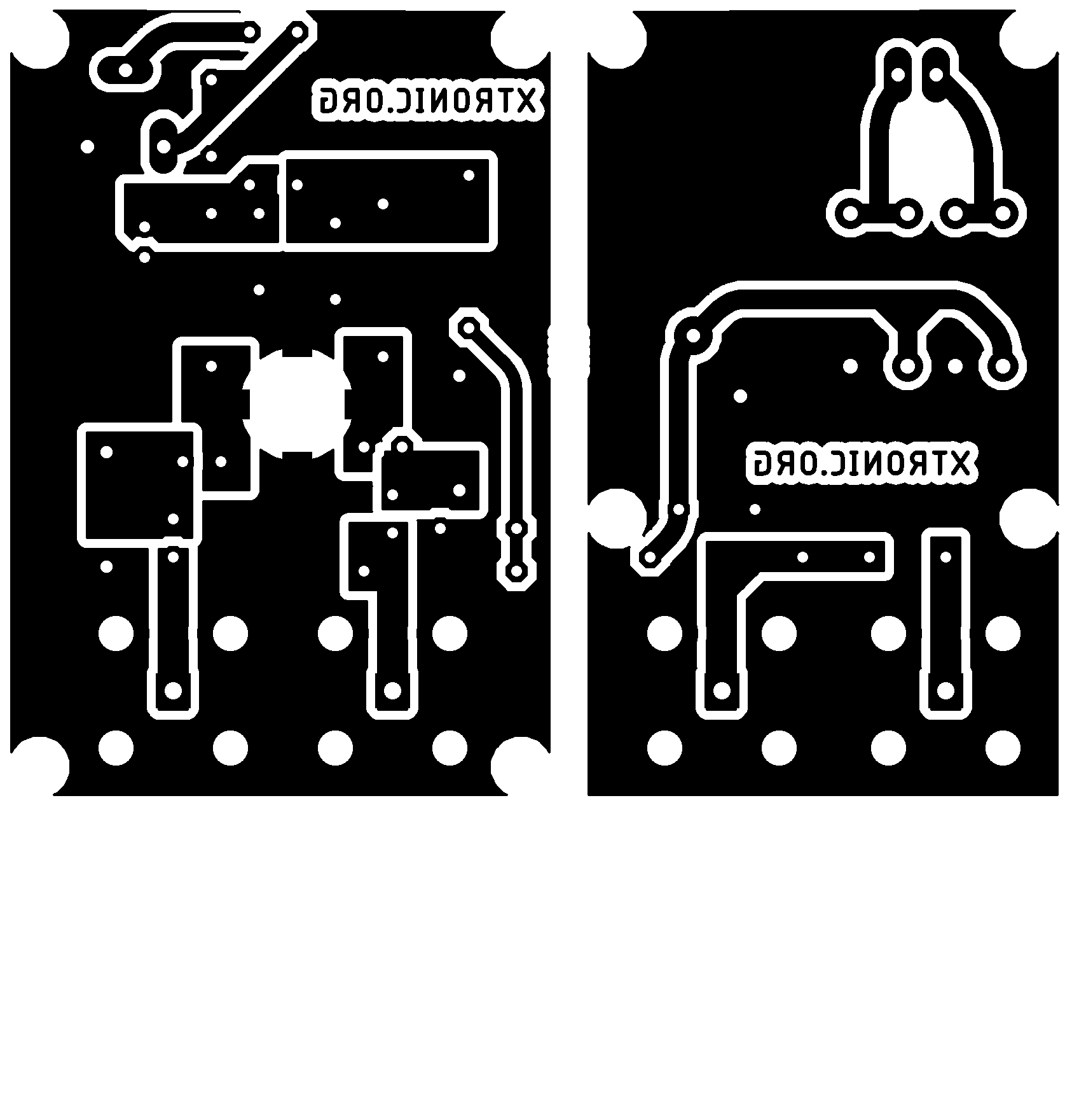
RF Amplifier Printed Circuit Board You can download a pdf file which is the black PCB. The PCB is mirrored because the printed side side should be faced down the board during UV exposure. To the right you will find a pic showing the assembly of all components on the same board.
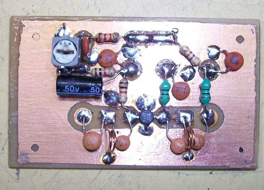
This is how the real board should look when you are going to solder the components. It is a board made for surface mounted components, so the copper is on the top layer. I am sure you can still use hole mounted components as well.
Grey area is copper and each component is draw in different colors all to make it easy to identify for you. The scale of the pdf is 1:1 and the picture at right is magnified with 4 times. Click on the pic to enlarge it.
Low-Pass Filter Some of you might want to add a low-pass filter at the output. I have not added any extra low pass filter in my construction because I don't think it is needed. You can easy find several homepages about low pass filter and how to build them.
-


9 Nisan 2012 Pazartesi


7 Watt PLL fm verici
-
- Arkadaşlar hazırlanmış olan 7watt pll projesini aşagıdaki linkten indirebilirsiniz.
Tüm Dosyalarını Aşagıdaki Resime Tıklayarak indirebilirsinz:
-

8 Nisan 2012 Pazar
8 Ohm 45 Watt, 4 Ohm 70 Watt Mosfet Amfi Devresi
-
8 Ohm 45 Watt, 4 Ohm 70 Watt Mosfet Amfi Devresi
-
8 Ohm 45 Watt, 4 Ohm 70 Watt Mosfet Amfi Devresi
-


Circuit Diagram and Filter 1.3-5W Power RF Amplifier Trans FM
-
Circuit Diagram and Filter 1.3-5W Power RF Amplifier Trans FM
- A amplifier of force RF for the FM , is always essential for the amateur that wants it strengthens some small transmitter, that likely already it has manufactured or has been supplied ready. The present circuit can give 50-60W RF force of expense, with control smaller than 15-20W in the region of frequencies of FM, that is to say in the 88-108MHZ. Transistor that we selected for this manufacture is the BLY90, that has gain 5dB.
-
circuit audio power amplifier circuit three channels of 25W mute stand-by circuit lm4782
-
circuit audio power amplifier circuit three channels of 25W mute stand-by circuit lm4782
- Circuit audio power amplifier using integrated lm4782 overtureTM for three channels of 25W with mute and stand-by
LM4782 is audio amplifier of three channels capable to supply 25W of potency for channel.
LM4782 uses the system of protection of National Self Peak Instantaneous Temperature (˚Ke) (SPiKeTM). Spike protects the exit of the lm4782 of on tension on load, short of the source for gnd, temperature protection and picks instantaneous of temperature. Each amplifier of the lm4782 has a mute circuit and internal stand-by, that can be controlled by logic it expresses. LM4782 can be configured to be used in bridge or in parallel way without complications, it exists several ways to use integrated him. To know more on spike it seeks for AN-898 in the site national.com .
Description of the operation of the circuit of the amplifier with lm4782
The circuit described here it is treated of the application suggested by the national semiconductors for an amplifier of potency of three channels with having integrated lm4782. To determine the heat-sink to be used it sees the datasheet of the lm4782.
In the way stand-by the drain of current of the source VCC is less than 30µA for all amplifiers and chain drained of the source VEE is typically of 8mA.
Bypassing Capacitors
To eliminate possible oscillations or instability in low frequency high frequency either is used a capacitor electrolytic or of tantalum to absorb variations in low frequency and a ceramic capacitor to prevent feedback in discharges frequencies. those components are placed in the power lines.
Filter high raisin
The combination of it Laughs with ci it creates a filter high raisin. The frequency answer is determined by those two components. The point of -3dB can be found using the equation below:
fi=1/(2ÀRiCi) (Hz)
If a capacitor of blockade dc be used, there is another filter it passes discharge servant with the combination of Cin and Rin. When great values of Rin are used it can happen oscillations in the exit.
To determine the type of the heat-sink and other assembly configurations it sees the datasheet of the lm4782.
Source for the circuit
That proposed circuit requests a symmetrical source of +-25volts that is capable of ?¤ “teão is necessary that is regulated. Just use a good transformer, rectificators and great capacitors of filter of at least 10000µF. The transformer uses transformer torodal preferably, they exist virtual stores that sell transformers and they dispatch for the whole brazil.
Schematic of the circuit of the potent amplifier with lm4782
-
1500W power amplifier circuit diagram (1500 W anfi devresi )
-
1500W power amplifier circuit diagram (1500 W anfi devresi )
-
This is a very high 1500W power amplifier circuit diagram by Rod Elliott. The circuit is built using 10 pairs of power transistor MJ15024 and MJ15025 (or MJ21193/MJ21194), then it will use 20 pieces of power transistor for final amplification.
With very high power audio output, then of course it will need power supply with high power output. This amplifier require dual output power supply 130V.
-

Amplifier Protector (Anfi Koruyucu Devresi)
-
Amplifier Protector (Anfi Koruyucu Devresi)
- Now you can protect your HiFi amplifier from damage due to excess heat. This circuit will cut off the power to the amplifier board at the moment it senses a high temperature. It automatically connects power when the temperature returns to normal. The circuit uses an NTC Thermister as heat sensor and it also has audible warning and reset provisions
D.Mohan kumar
The circuit uses the popular timer IC NE 555 as a temperature controlled switch. Its trigger pin 2 is connected to a potential divider comprising VR and the NTC Thermister. Thus the voltage level at pin 2 depends on the resistance of Thermister and the setting of VR. NTC (Negative Temperature Coefficient) Thermister has high resistance in normal temperature and the resistance decreases when the temperature increases. The Threshold pin 6 of IC is used to reset the IC if needed. When the pin 6 gets higher voltage than pin 2 IC will reset and output becomes low. Power to the amplifier board is given through the Normally Connected (NC) contacts of the relay and the switch S2. So that power to the amplifier board will be available through the NC contacts of the relay and S2 when the relay is in the de-energized state. Resistance of the Thermister is set by VR so as to keep the trigger pin 2 of IC high at normal temperature. When the temperature inside the amplifier cabinet increases, resistance of Thermister decreases so it becomes conducting. This makes the trigger pin 2 of IC low and its output becomes high. T1 conducts, so that the relay energizes and buzzer beeps. This will break the power supply to the amplifier board. The relay will de-energize automatically when the temperature returns to normal
Keep Thermister near the Heat sink of the amplifier IC. Adjust VR for the particular temperature level at which relay energize.
Designed by D.Mohan kumar
-

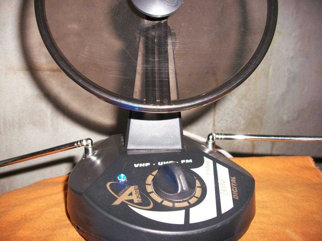
Wideband DTV UHF Antenna TV Amplifier Circuit using transistor 2sc3358 – Antenna amplifier for digital tv band
-
"2sc3358 Transistörü kullanılarak Geniş Bant DTV UHF Anten TV Amplifikatör Devresi "
-
- This HD TV UHF wideband amplifier(Ultra High Frequency amplifier) has a total gain of 10 to 15 dB in the 400 – 850 MHz domain frequency so it can be used where the tv signal is weak.
- T1 -Transistor 2sc3358
- C1 – 10µF/35v
- C2,C9 – 1nF
- C3 ,C4 – 10nF
- C5,c6,c7,c8 – 10pF
- R1 – 470 Ohms
- R2 – 2.2 K
- R3 – 1Kohms
- P1 – 5Kohms
- L1,L2 – 2 turns 22AWG , 3mm Ø.
- L3,L4 – 10uH or 10 turns, 0.2mm Ø on ferrite..
- 12 volts special power supply.
For this UHF antenna tv amplifier to work correctly you need to cut the components pins as short as possible. C1, C2, C6, C7 are SMD type ( surface mounted ). This antenna tv amplifier or uhf wideband amplifier need to be build inside of a metal box and then connected close to the tv antenna.
Prototype pictures (Prototip resimler)
Antenna HD TV UHF band amplifier circuit schematic (Anten HD TV UHF bandındaki amplifikatör devre şeması)
PCB layout for Wideband HD TV UHF Antenna TV Amplifier Circuit using transistor 2sc3358 (Baskı Devresi)
The power supply is a simple 12V stabilized source. The antenna tv amplifier can be connected directly to the power supply thru coaxial cable of the tv antenna but you need a 10 – 100uH coil on the alimentation line. The tv set will be connected to the uhf amplifier thru a small coupling capacitor.
Adjusting is easy, just bring the P1 to the middle and then adjust it untill you obtain the best tv image quality.
Digital Tv antenna UHF amplifier components (Devrede kullanılan malzeme listesi):
2sc3358 Transistörü kullanılarak Geniş Bant DTV UHF Anten TV Amplifikatör Devresi
-
Transistörlü anfi devresi tasarlama programı (Transistor Amplifier Circuit Designer Software)
-
Transistörlü anfi devresi tasarlama programı (Transistor Amplifier Circuit Designer Software)
-
- TransistorAmp BJT Transistor Amplifier Circuits Designer Software
- common-base-circuit
- common-emitter-circuit
- common-collector-circuit
For the design of transistor amplifiers there is a new software available: TransistorAmp. With TransistorAmp you are able to create your individual transistor amplifier with a few mouse clicks. TransistorAmp is freeware.The tool TransistorAmp has a very easy to use user interface. You start every design with the menu item “New Amplifier”. In the pull-down-menu you choose your desired circuit. You can choose between,
After that you get a dialog, where you have to put in all parameters of your amplifier.
For the selection of the transistor type you can click on the button “Select transistor type from list”, and you will see a list of all supported transistor types. TransistorAmp supports some thousand transistor types. Select your desired transistor type there and click on OK. The selected transistor type will then be displayed in the dialog.
TransistorAmp software.zip
alternatif
FileSwap.com : TransistorAmp software.zip download free
-


7 Nisan 2012 Cumartesi
Sprint-Layout 4.0 Kullanımı (video)
-
Sprint-Layout 4.0 Kullanımı (video)
-
Elimden geldigi kadar anlattim eksiklerim vardır onlarıda siz cozersiniz zati cok basit ve guzel bir program
acılmaz ise codec sorununuz vardır buradaki codec yukleyiniz Download Video Codecs
+ Olarak standart kurulumda gelen malzemeler yanısıra kendi yaptıgım ve netten buldugum malzemeler..
FileSwap.com : spirint_layout_kullanimi.rar download free
Son Düzenleme guclusat™ tarafından Bugün 19:27 de yapıldı.. Sebep: Linkler güncellendi
-

Ariston Egis 24 Kombi Arıza Işıkları, Ariston Egis Arıza Kodları
-
Ariston Egis 24 Kombi Arıza Işıkları, Ariston Egis Arıza Kodları
-
Ariston EGIS 24
Ariston EGIS 24 FF
Ariston EGIS 24 CF Kombi Arıza Işıkları
Arıza Kodları, Arıza Işıkları
90 Derece ve Alev Çarpı Işığı Direk Yanıyor:
Çözüm: Aşırı Isınma Mevcut. Radyator petekleriniz kapalı olabilir, en az 3 petek vanasının açık olması gerekir.
50 derece, 60 derece ve baca ışığı yanıp sönüyor:
Çözüm: Yetersiz su devirdaimi.
Kombinizin subasıncını kontrol edin tavsiye ettiğimiz degerler 1.5 ile 2.0 arasında olmasıdır.
-

Bosch Yoğuşmalı Kombi Arıza Kodları ve çözümleri
-
Bosch Yoğuşmalı Kombi Arıza Kodları ve çözümleri
- Bosch Gazlı, Yoğuşmalı Kombi
Bosch Classic Condense
Bosch ZWB 28 - 3C.. (B1 RDC 28 41 H)
Bosch Yoğuşmalı Kombi Arıza Kodları ve çözümleri
A7 Arıza Kodu: Sıcak kullanım suyu sensörü (DHW-NTC) arızalı.
Kullanım suyu sıcaklık sensörünü ve bağlantı kablosunu kontrol edin.
(Sıcaksu NTC sini değiştirin.)
A8 Arıza Kodu: BUS iletişiminde kesinti.
Bağlantı kablosunu ve termostatı kontrol edin.
b1 Arıza Kodu: Kod anahtarı algılanmıyor.
Kod anahtarını yerine doğru takın, numarasını kontrol edin, gerekirse değiştirin.
b2 veya b3 Arıza Kodu: Dahili hata.
Teknik Destek Alınız.
C6 Arıza Kodu: Fan çalışmıyor.
Fan Motoru Arızalı Değiştirin.
CC Arıza Kodu: Dış hava sensörü algılanmıyor.
Dış hava termostatını ve bağl. kablosunu kontrol edin.
d3 Arıza Kodu: 8 ve 9 köprüsü eksik veya harici sıcaklık limitörü devreye
girmiş.
Soket yerine oturmamış, köprü eksik, yerden ısıtma sıcaklık sınırlayıcısı devreye girmiş.
d5 Arıza Kodu: Harici (extern) sıcaklık sensörü arızalı (Denge kabı).
Harici (extern) sıcaklık sensörünü ve kablolarını kontrol edin.
E2 Arıza Kodu: Gidiş suyu sıcaklık sensörü arızalı.
Sıcaklık sensörünü değiştirin.
E9 Arıza Kodu: Isı bloğundaki emniyet termostatı (STB), atık gaz emniyet sensörü veya düşük basınç emniyet şalteri devreye girmiş.
EA Arıza Kodu: Alev algılanmıyor.
Kombinizin Gaz giriş vanası açık mı ? Gaz giriş basıncını, şebeke bağlantısını, ateşleme elektrodu ve kablosunu, iyonizasyon elektrodu ve kablosunu, atık gaz borusunu ve CO2 kontrol edin.
F0 Arıza Kodu: Dahili hata.
Genel Arıza Teknik Destek Alınız.
F1 Arıza Kodu: Dahili hata.
Genel Arıza Teknik Destek Alınız.
F7 Arıza Kodu: Cihaz kapandığı halde alev algılanmaya devam ediyor.
Elektrodları kontrol edin. Atık gaz yolu açık mı? Anakart nemli olup olmadığını kontrol edin.
FA Arıza Kodları: Gaz kesildiği halde alev algılanmaya devam ediyor.
Iyonizasyon elektrodunu ve gaz armatürünü kontrol edin. Kondens suyu sifonunu temizleyin. Atık gaz yolu açık mı?
Fd Arıza Kodları: Yanlışlıkla vede uzun süreli olarak reset butonuna basılmış.
Reset butonuna tekrar basın.
-

Circuit of of power audio amplifier with ic tda2003 for 10 Watt potency
-
Circuit of of power audio amplifier with ic tda2003 for 10 Watt potency
-
- Circuit of of power audio amplifier with tda2003 for 10 Watts potency
- R1:220 Ω
- R2: 2.2Ω
- R3: 1Ω 1 watt
- Rx: 39Ω See the datasheet paw to alter the value of Rx
- C1: 2.2µF 25V electrolitic
- C2:470µF 35V electrolitic
- C3:0.1µF polyester or ceramic
- C4:1000µF/35 V electrolitic
- C5: 100nF polyester or ceramic
- C6: 100µF 35v electrolitic
- Cx 39nF See the datasheet paw to alter the value of Cx
- IC1: TDA2003
TDA 2003 has a better performance than the tda2002 using the same configuration of pins. Additional characteristics in relation to the tda 2002, it demands few components external, easy assembly, it is a low cost solution for an audio amplifier. A mounted amplifier with tda2003 presents protection against short of the pins with the earth. The good of setting up an amplifier with tda2003 is that he easy of being found at the market, even for who is far away from the great centers, has the possibility to do to buy him/it integrated by the internet. The tda2003 can be fed by batteries by a long period.
Description of the circuit of the amplifier of 10 watts simple source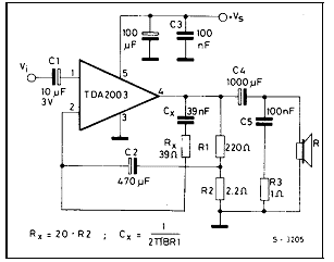
It is treated of an assembly easy of being accomplished what is necessary it is just a tda2003 and one more half dozen of components.
To facilitate the assembly the circuit it counts with a circuit plate printed.
Schematic of the amplifier with tda2003
Suggestion of printed circuit board for assembly of the amplifier with tda2003. Real size.
PCI side of the components to guide in the assembly of the amplifier with tda2003.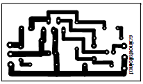
lists of components for assembly of the amplifier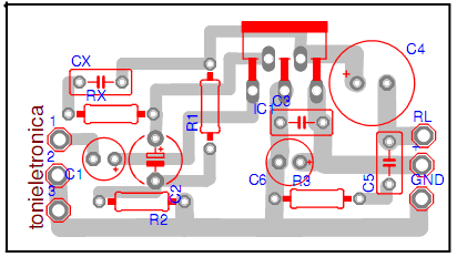
Resistors:
Reference: Tda7294 St microelectronics datasheet.
www.st.com
-


ABCD Harf Birleştirme Oyunu
-
ABCD Harf Birleştirme Oyunu
-
- ABCD Harf Birleştirme Oyunu Çok Basit ve eğlenceli bir oyundur Tavsiye ederim.
- ABCD Harf Birleştirme Oyunu
-

6 Nisan 2012 Cuma


12 Volt DC Floresan Lamba Sürücü devresi (12 Volt DC Fluorescent Lamp Driver )
-
12 Volt DC Floresan Lamba Sürücü devresi (12 Volt DC Fluorescent Lamp Driver )
-
- Q1 must be installed on a heat sink.
- A 240V to 10V transformer will work better then the one in the parts list. The problem is that they are hard to find.
- This circuit can give a nasty (but not too dangerous) shock. Be careful around the output leads.
C1 100uf 25V Electrolytic Capacitor
C2,C3 0.01uf 25V Ceramic Disc Capacitor
C4 0.01uf 1KV Ceramic Disc Capacitor
R1 1K 1/4W Resistor
R2 2.7K 1/4W Resistor
Q1 IRF510 MOSFET
U1 TLC555 Timer IC
T1 6V 300mA Transformer
LAMP 4W Fluorescent Lamp
MISC Board, Wire, Heatsink For Q1
Notes:
-


High Voltage Converter Circuit
-
High Voltage Converter Circuit
-
- Starting from a 30 volt power supply this high voltage converter circuit can deliver a voltage between 0 to 3 kV (version 1) or from 0 to 10 kV (version 2).
IC 4011 gates N1 … N3 are connected as astable multivibrator that commands the Darlington T1/T2 with an rectangular impulse of 20 kHz.
The transistors cannot be brought to saturation because of the low current that goes through them which will result in a very short block period. The rapid blocking of the transistors will produse an impulse of almost 300 V in the transformer’s T1 primary winding. This voltage is multiplied by the numbers of turns from the secondary winding.
For the first version it uses a monophased rectification. The second one uses a cascade rectifier from an old TV set and it delivers a 3 times higher voltage.
3 kV/10 kV High-Voltage Converter Schematic
-
5 Nisan 2012 Perşembe
MC145170 PLL fm verici devresi
-
MC145170 PLL fm verici devresi
-
Power Output250mWFrequency Output87.5MHz to 108 MHzFrequency Step10KHzPhase Noise-103dBc/HzFrequency Stability+/- 400HzHarmonic Filtering (Except H2)<-60dBcSpurious Emissions<-70dBcModulationDirect Frequency ModulationMPX Input Response+/-0.5dB 30Hz to 80KHzMPX Input Level300mV RMS MinPower Supply14 to18V
-

All digital PLL for RF transmitter(pll fm verici devreleri döküman)
-
All digital PLL for RF transmitter(pll fm verici devreleri döküman)
- All digital PLL for RF transmitter(pll fm verici devreleri döküman) pll fm verici devreleri için güzel bir döküman ingilizce olarak hazırlanmıştır.
-
4 Nisan 2012 Çarşamba
600 Watt Ses Amplifikatör devresi (Schematic 600W Audio Amplifier)
-
600 Watt Ses Amplifikatör devresi (Schematic 600W Audio Amplifier)
-
600 Watt Ses Amplifikatör devresi (Schematic 600W Audio Amplifier)
POWER :
Maximum Output power @ 8ohms : 300watt
Absolute max power supply voltage :±38V to ±40V
Recommended power supply voltage :±30V to ±35V
-

Switching Power Supply
-
-
This is a Somewhat Experimental Circuit and I Especially designed this circuit for those persons that want to Dabble in Switching Power Supply Designs.
This Circuit is based on a UC3843 Integrated Circuit. It does Not allow for Feedback control of the output voltage. The output voltage is totally determined by the "Turns Ratio" in Transformer "T1". The Useable, Continuous Power Output is approximatey 25 watts or so. It could be used as a small Power Supply or a Battery Charger. In the proto I made, T1 has a Primary Inductance of about 1 mH. This requires 33 turns of 26 or 28 AWG Wire wound on the Bobbin First. (About One Layer if you use the 28 AWG, or a Bit over one layer if you use the 26 AWG) To get this 1 mH inductance using this core, also requires this ferrite to have a total gap of 0.005 inches. Or 0.0025 gap on each leg of the core. ** I can Pre-Gap this for you if you buy the core and bobbin from me. The Supply voltage is 117 Volts AC. When Rectified it produces a DC Supply of about 165 Volts. The Output Voltage is basically determined by the Turns ratio to the primary winding and to that 165 volts. To Get out 12 Volts, you will require about 2.4 Turns on the Secondary. I used 3 Turns, just to make it easier. This Winding is Wound Over top of the Primary, Using a Good Insulation layer between it and the Primary. This Insulation Material should be for 3,600 Volts for shock hazzard safety. 165 / 33 = 5 Volts per Turn Therefore 12 \ 5 = 2.4 turns. However you can also use as many turns as you want, to get Whatever Voltage you desire. As another Example, If you wanted 30 volts out 30 / 5 = 6 Turns on this Secondary. On the transformer I made, I used a Bifular wound output to give me Full wave rectification using just two diodes. NOTE: Bifular Winding is Two Wires wound Simutanously, side by side, Than joined properly phased to give a Center tapped output. ** Or you could just wind a Single Output and use a Bridge rectifier. ** OR just a Single Diode, for Half Wave Rectification. ** Or No Rectification for an 80 Khz Output. These are some of your Choices to make. In the transformer, there is a 3rd winding. The 56 K, 2 Watt Resistor only supplies a Start Up power for the UC3843. Once the circuit is running, the Uc3843 actually gets its power from this 3rd winding. I used 6 turns of 28 AWG. It gets wound over the Secondary winding with a thin layer of insulating material between it and the output winding. Resistor "IX" is a 1 or 2 watt Current Limit Resistor to protect the IC. NOTE: Current to the IC MUST NOT EXCEED 30 Ma. In the circuit I built, a "100 ohm" resistor was used. ** But if in Doubt, use a somewhat Higher Resistance and than reduce it till you get a Reliable Starting when the 117 volts is applied to the circuit. (If this resistor is Too High in value, the circuit will somewhat Oscillate, giving a Pulsing output.) Materials and Parts. I can supply the Circuit Board. The Ferrite Core and Bobbin that I show. The UC3843 IC. A Fuse and the Fuse Clips for the PCB. Some of the Resistors As well as a "Nomex" Insulating Material for between the layers. NOTE: Sorry, But I do Not supply any of the 2 Watt resistors or the Higher Voltage Capacitors. I don't stock that many of these higher wattage ones, same with the caps. (Actually I had to Parallel some smaller resistors in this proto to get the wattage.) Also, The Actual Winding of this transformer is up to you. I have done it once and thats enough for me. It's Not that this transformer is that difficult to wind, but I wound a lot of proto-type transformers and coils and it gets boring doing it over and over again.
There will probably be Updates to this article. As I Probably Missed out some stuff.
The Schematic
-


Adjustable power supply
-
- As I carry out a lot of repairs on C.B. and audio equipment, I need a variable power supply with very good current limiting and protection. The circuit I designed for this purpose is shown in the diagram below. This power unit will deliver a current from zero to about 4.25A at a voltage from zero to about 23V. With the component values shown, the short circuit protection is 400 mA, but it can be set below this figure; for instance, an LED can be connected directly to the power supply and the current adjusted to light it without destroying it. The unit is not difficult to build, and in my opinion it outperforms many commercial power supplies. Mine has been in use for more than a year, and has given no trouble at all in that time.
-
Portable Power Supply
-
- Here is an ideal Power Supply Unit for trouble shooting the circuit boards. It gives Five and Nine volt regulated DC from a Rechargeable battery. It is portable and handy and can also functions as a Mobile Charger. Transformer less power supply is used in the circuit to charge the battery from mains. This makes the unit compact and light weight.
The circuit has two sections. The front end is a charger section with capacitor C1 as the main element. It is an X rated 400 Volt AC capacitor that reduce the 230 volt AC to low volt AC through the Rectance property. Low volt AC is then rectified by the full wave bridge rectifier comprising D1 through D4. Resistor R1 bleeds the stored current from C1 when the power is disconnected. Resistor R2 reduces the inrush current into the circuit at power on. Rectified AC is then made ripple free by C2 for charging the 9 Volt Rechargeable battery. Zener diode ZD regulates the charging voltage to 15 volts and resistors R3 and R4 gives around 80 to 100 mA charging current. Diode D6 prevents discharge of battery back to the bridge.
Variable resistor VR1 and transistor T1 forms a voltage indicator. LED lights when the battery is fully charged and goes off if the battery voltage reduces below 7 volts. VR1 sets the low voltage level. This prevents deep discharge of battery. When the circuit is connected to mains and S1 is in ON position, battery charges through D5, R3, R4 and D6. When the unit is unplugged from mains, 9 volt output power will be available from the battery. Voltage regulator IC1 gives 5 volt DC. Switch S2 can be used to select 9 v or 5v output.
Portable Power Supply Circuit diagram
-

Self switching Power Supply
-
- One of the main features of the regulated power supply circuit being presented is that though fixed-voltage regulator LM7805 is used in the circuit, its output voltage is variable. This is achieved by connecting a potentiometer between common terminal of regulator IC and ground. For every 100-ohm increment in the in-circuit value of the resistance of potentiometer VR1, the output voltage increases by 1 volt. Thus, the output varies from 3.7V to 8.7V (taking into account 1.3-volt drop across diodes D1 and D2).
Another important feature of the supply is that it switches itself off when no load is connected across its output terminals. This is achieved with the help of transistors T1 and T2, diodes D1 and D2, and capacitor C2. When a load is connected at the output, potential drop across diodes D1 and D2 (approximately 1.3V) is sufficient for transistors T2 and T1 to conduct. As a result, the relay gets energised and remains in that state as long as the load remains connected. At the same time, capacitor C2 gets charged to around 7-8 volt potential through transistor T2. But when the load is disconnected, transistor T2 is cut off. However, capacitor C2 is still charged and it starts discharging through base of transistor T1. After some time (which is basically determined by value of C2), relay RL1 is de-energised, which switches off the mains input to primary of transformer X1. To resume the power again, switch S1 should be pressed momentarily. Higher the value of capacitor C2, more will be the delay in switching off the power supply on disconnection of the load, and vice versa.
Though in the prototype a transformer with a secondary voltage of 12V-0V, 250mA was used, it can nevertheless be changed as per user’s requirement (up to 30V maximum. and 1-ampere current rating). For drawing more than 300mA current, the regulator IC must be fitted with a small heat sink over a mica insulator. When the transformer’s secondary voltage increases beyond 12 volts (RMS), potentiometer VR1 must be redimensioned. Also, the relay voltage rating should be redetermined
-

3 Nisan 2012 Salı
12V dc power supply schematics
-
12V dc power supply schematics
- 12V BD139 power supply circuit
LM7812 power supply schematic
A very simple PS circuit with the basic 3 Amper version of LM7812 IC.
LM317 variable power supply circuit
2N3055 adjustable power supply schematic
This PS circuit has a over-current protection and a good stabilized voltage. It can deliver up to 1.6 A.
-


0 - 12 volt,500ma ayarlı ve regüleli güç kaynağı Devresi
-
0 - 12 volt,500ma ayarlı ve regüleli güç kaynağı Devresi
- Deney masanızdaki pil ve adaptörünüzü bu çok amaçlı güç kaynağı ile değiştirebilirsiniz.
Devrenin Gerçekleştirilmesi:
Bütün güç kaynaklarında olduğu gibi yapımı özel bir dikkat gerekmektedir.Yanlız güç transistörü 5x5 cm.lik bir soğutucu üzerine monte edilmeli.soğutucunun devrenin başka kısımlarına değmemesine dikkat edilmelidir.
-


L200 Güç Kaynağı
-
-
Notlar
Çok yönlü 5 pin L200C regülatör tek bir pakette iki akım ve gerilim regülasyonu sunuyor. IC ayrıca 60 Vdc kadar voltaj koruması üzerinde termal kapatma ve giriş özellikleri. Paket ayrıca bir PCB üzerine montaj için düz iğneleri vardır L200CV olarak kullanılabilir. Yukarıdaki devreyi dolayısıyla 1 amp, RSC = 0.45 ohm akım sınırlama bulunmuyor. Çıkış voltajı 36V 2.85V arasında değişkendir. 36V kadar gerilimler için daha sonra giriş gerilimi Vcc 40V olmalıdır. Besleme gerilimi gerekir her zaman bir kaç volt maksimum çıkış voltajı daha yüksektir. Eğer 9 volt akım sınırlı PSU yapmak istedim Eğer giriş voltajı 12 Volt en az olmalıdır.
Maksimum Güç Tüketimi
L200 ısı dağılımı miktarını azaltmak için sınırlı iç sahiptir. Bu iç birleşme sıcaklığı 150 ulaştığında olur ° C Veri, ama güvenli çalışma alanının bir grafik var maksimum çıkış 2 amper, giriş voltajı eksi çıkış gerilimi farkı az 20 Volt olmalıdır mevcut çizim eğer.
Özellikleri:
DC Giriş Gerilimi: 40V max.
Tepe Giriş Voltajı: 60V max. 10ms için
Çıkış voltajı: 2.85 ile 36V
Çıkış Akımı Aralığı: 0.1 2A
Geçerli sakin: 4.2mA
Çıkış Gürültü: 80uV
L200 regülatör birçok versiyonu var; L200, L200C, L200CH, L200CV. Bunların hepsi aynı regülatör aslında. değişkenler arasındaki temel farklar termal kavşak sıcaklık ve bacak yapısı vardır.
L200 için, işletme birleşme sıcaklığı -55 150 ° C
L200C işletim birleşme sıcaklığı -25 ila 150 Â ° C
V dikey açılımı ve en sık görülen durum tarzıdır; kullanılabilir sağ tarafta gösterilen pentawatt paketi gibi. H ve yatay açılımı L200 ve pimleri PCB montaj için dik yamuk. L200T ve L200CT değil, aynı zamanda mevcut bir TO3-4 düzen olarak, bu pinout aşağıdaki bağlantıyı veri sayfasında görülebilir.
-


Kaydol:
Kayıtlar (Atom)